

On Saturday May 20th, 2023 the 17th Ninja Penguin event kicked off with a night of art, dancing, and celebration all themed around cyberpunk penguins.
This year featured artwork by Pinguino, David Shorey, Random, and myself as well as music by Keith Myers, James Ford, Mass Accelerator, Ninjula, Headshot, GRAPHIXX.X, PBOB, Bubbles, and Michael Walker.
The past couple of years, I've done some projection mapping in the space which I curate throughout the night. This year we wanted to do something a little different and the answer quickly came to us: a penguin pendant.
Now the astute amongst you might say "That's not a pendant! That's a printed circuit board (PCB)!" and you would be correct. You see, given that this is a crowd with an affinity for things that glow and blink I felt that there could be a possibility of adding a challenge and sweetening the deal for the curious user.
Before I go too deep though, if you got one of these and want to take a stab at assembly you will want to bookmark the following link: Tool: Interactive Bill of Materials
As mentioned, the pendant is actually a printed circuit board. For Ninja Penguin the manufacturing capabilities fit us perfectly. Both Pinguino and myself tend to stick to vector artwork, and as mentioned in https://brianredbeard.com/blog/the-trouble-with-gerbers/, the at the core of all printed circuit board manufacturing is RS-274 (aka "gerber") - an ASCII based vector format.
I'm about to tell you a lie. Just go with it. The purpose of the lie is just to make it easier to visualize.
The idea basically becomes to think about your artwork as a spot-color stackup. Each color you desire to "print" is going to happen to map to a layer in the PCB stackup as a "mask". Each mask is going to be either to hide and show various parts of the layers. 1
Below we can see the layers for our "stackup":
To help with the assembly I generated output using InteractiveHtmlBOM.
The output is a webpage that you can use to see the parts and placement. You can also click on the parts to mark them as "sourced" or "placed" (these can be helpful when you are going through the list of parts and trying to figure out what you've got in your scrap bin and what you'll still need to go hunting for).
The basics of the circuit is that it's a circuit that I cribbed from the Department of Education's Open Textbook Pilot Project. The cool part is that you can dive deep on that page and see the details of the circuit.
The circuit is a simple one. It's a 555 timer based clock that is fed into a PNP and NPN transistor pair. The PNP transistor is used to control the brightness of the LEDs. The NPN transistor is used to control the blink rate of the LEDs. Or at least it's something like that. YOLO.
I took advantage of the fact that there are newer 555s which handle much lower logic levels but, really you could use whatever you wanted or had on hand.
I also want to warn you that I was a bit of a bastard. There are a couple of 0402 parts on there. Did there need to be? No. I just did that on the infinitesimally small chance that we maybe possibly kindof might have had them manufactured. Just saying. Had I done that the board house I was considering using (who I will not be mentioning because I'm neither a shill nor am I a huge fan of their work) would have had all components in stock and reeled up for the pick and place.
The list of parts is as follows:
| Reference | Part | Value | Footprint |
|---|---|---|---|
| C1 | Capacitor | 1 µF | |
| C2 | Capacitor | 100 µF | 1206 |
| C3 | Capacitor | 100 µF | 1206 |
| R1 | Resistor | 1.5 MΩ | 0603 |
| R2 | Resistor | 47 kΩ | 0402 |
| R3 | Resistor | 2.2 kΩ | 0603 |
| R4 | Resistor | 620 Ω | 0603 |
| D1 | LED (Counterpost) | RED | counterpost |
| D2 | LED (Counterpost) | RED | counterpost |
| D3 | Diode | SS14 | D_SMA |
| U1 | 555 Timer | XL555 | SOP-8 |
| BT1 | Battery Cell Holder | 2032 | 2032 Coin Cell |
| Q1 | PNP Transistor | S8550 | SOT-23 |
| Q2 | NPN Transistor | S8050 | SOT-23 |
Literally every one of these parts are probably in a junk box at your local hacker space (or in your closet).
To perform the assembly you'll need some tools. A soldering iron would be the bare minimum (and also the most challenging). Other options include your hot plate or other re-flow type of system. I personally use a hot plate and a soldering iron for tuneup. I want to be clear: THIS IS NOT A TUTORIAL ON SOLDERING.
If you've never soldered anything before, appeciate the natural beauty of that electroless nickel immersion gold finish. There's an video below to tickle your blinky blinky.
As to performing the assembly, my general process for assembly looks like this. First, get some double sided tape. Take a piece of it and put it directly onto the table in front of you. You'll then take your various cut-off strips of parts and make sure they're stuck to the tape. This will then keep them from sliding away when you're trying to peel the celophane off with a pair of tweezers.
When you are peeling off the celophane from a part, try to only peel back enough to expose the part. That can help tiny specks from flying when a table gets bumped.
Now the idea is that you want to get the parts soldered to their respective places. For that, check out the rendered interactive bill of materials (If you want to see how fancy InteractiveHtmlBom is, check out the documentation.)
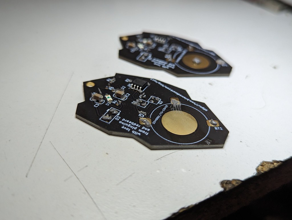
Now, for me, I just place the board on the table face down. Grab a syringe of solder paste and place a tiny dab on every pad. So, at this point I've got:
- double stick tape down
- the board is on the tape
- i've got a little slice of parts stuck to the tape
- i've taken a solder syringe and put down dabs of solder on every pad
- i've used tweezers to remove the parts from their strips and and place them in the correct spots (using the bill of materials as a reference)
Thus, it looks a bit like this:
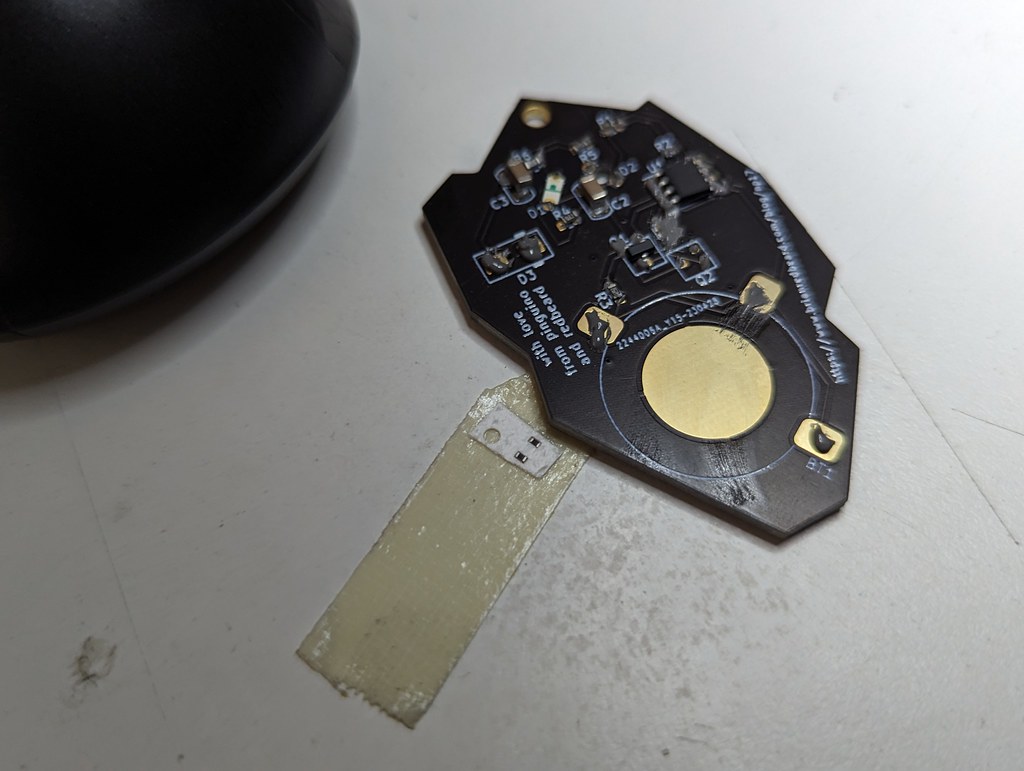
Or from a different angle (before I had placed D3, R3, the transistors and some other parts):
After you've finished placing all of your parts you'll want to then perform the "reflow" process. I did this on a tiny hotplate and recorded a video which can be seen here:
References:
- I don't know what solder paste to buy? - Lady Ada has a video for that.
- If you're just curious about what the process looks like professionals will stencil solder on in a screen printing like process. Check out this EEVBlog tutorial (note: I linked it mid-way through so that folks focused on what the process looks like with a hot air gun can skip straight to the assembly part).
- My solder parts are blowing around when trying to do hot air rework. - Louis Rossmann has you covered.
Ninja Penguin has once again come and Ninja Penguin has once again gone.
I look forward to seeing everyone again next year!
-
I've spent a month imagining different ways of visualizing this. It's a pretty complex concept and I'm not sure if I've found the right way to visualize it. I think I may end up making a video about this soon. ↩︎